|
|
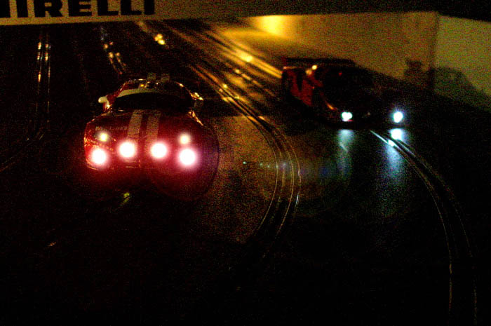 Let there be light! Many of you have asked and/or wondered how RfH builds the lights, flaming pipes, position/marker lights in mirrors and break lights. In this article you will receive an overview on the building blocks of our lights as well as some tips and tricks.
article is a work in progress
The Power Supply - Theory
The circuitry for the lights needs to be provided with constant power.
The power source is what you squeeze out of your controller while racing the car.
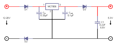
Looking at the electronics schema:
The left side is connected to the track via the motor wires.
To protect the circuitry diodes D1 and D2 are in place.
The voltage regulator MC7806 with its stabilizing capacitors Cin and Cout
brings the input voltage down to 6 Volts.
Diode D3 reduces this output voltage by another 0.6 to 0.7 Volts which is just right for
GoldCap capacitor C1. A GoldCap works like a rechargeable battery.
This is required to keep the lights on when no more power is coming from the track
(breaking, track call, flying, etc.)
With this power supply you've got an excellent basis for your slot car lights.
The Power Supply - Practice
Theory is all fine but how the heck are the components put together as shown in the schema?
A picture says more than a thousand words.
From the motor wires two fine train wires (red for plus and black for minus - stick to these
colors at ALL TIMES - believe me, it makes troubleshooting easier)
with the diodes D1 and D2 soldered in line are brought to pins 1 and 2 of the voltage regulator.
Though shalt not switch pins 1 (+in) and 3 (+out) of the voltage regulator!
It will work if you do - for a while - but the voltage regulator gets very hot and it will fry
itself to death in no time.
First prepare the voltage regulator[3] to fit the two
Tantalum capacitors Cin[1] and Cout[2] for soldering.
The pins are counted from left to right in [3]. When turning the voltage regulator on
its belly, the order changes - of course. I just wanted to mention it as I burnt my
fingers on a very hot regulator; caused by switching the +in and +out pins
I drill small holes into the pins of the voltage regulator to
hold the pins of the Tantalum capacitors.
[4] Now bend the pins of the Cout capacitor in a 90° angle so that it nicely fits
on the back of the voltage regulator. Make sure to bend it the right way so that the plus
pin - usually the longer one - goes into the left pin (pin #3).
[5] With the Cin capacitor bend only it's plus pin as we'll cut the negative pin to fit
it next to Cout's negative pin.
|
[1]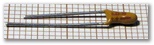 [2]
[2]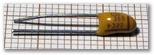
[3]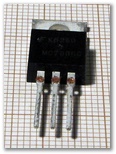 [4]
[4]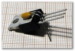
[5]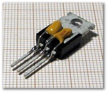
|
|
|
I usually start by soldering all wires to the voltage regulator first and keep working away
from it towards the diodes and the gold cap.
[more text and other pictures]
Simple Light Schema - Theory
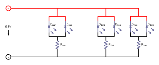
With the power supply in place you're ready for the cabling in the body with the resistors
and the LEDs. Lets take a look at the schema:
Our little power supply provides just over 5 Volts.
LEDs typically don't require or like such a high voltage and can be destroyed.
To bring down the voltage we use resistors.
The formula to calculate the right resistor value is pretty simple:

You'll have to lookup the LED's specification for the peak performance voltage (U) and
current (I) values. The values for the white high bright LEDs I've got are
Ityp=20mA and Utyp=3.6V.
The power supply gives us 5.3 Volts, hence we have to burn 5.3V-3.6V=1.7V.
Using these values in the formula we get:
R=1.7V÷0.02A=85Ω. This is for a single LED. For two LEDs in parallel the
current (I) needs to be doubled. The resulting resistor value becomes 42.5Ω.
Resistors don't exist in any value and you have to choose the closest match.
I never go under 100Ω for front lights and I always use one resistor per
two LEDs. For rear lights the resistor value needs to be much higher. I've got
red low current LEDs (Imax=20mA and Utyp=1.8V). For two LEDs
we get R=(5.3V-1.8V)÷(2×0.02A)=87.5Ω. But, now we have very bright rear mist lights
and that's very ugly. Here's where the fun begins: experiment with different resistor
values on a patch board. For such high bright low current red LEDs I usually end
up using 2200Ω resistors. I once even went up to 6700Ω to get the
perfect effect.
Simple Light Schema - Practice
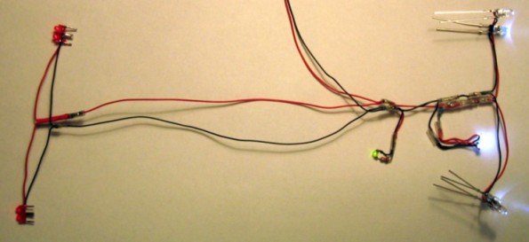
Picture shows the Dome S101 Racing for Holland cabling with four rear LEDs,
two times two front LEDs, two center surface mount device (SMD) LEDs and a
green cockpit LED..
What you want is as little as possible extra weight in your body. Don't run double
wires, say two plus (red) and two minus (black) wires from the center of the body
to each rear light. Instead combine such wires to the point where you have to split
them to reach each LED or group of LEDs.
Patch Board
With a patch board you can experiment to your hearts delight. The best thing is
that you don't need to solder anything. Before I start making a light kit I build
everything onto such a patch board. Once I'm happy with the resistor values and the
resulting brightness levels of all LEDs I start with the body cabling kit.
Flaming Pipes
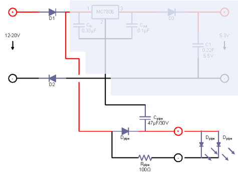
Here's the additional Flaming Pipes schema.
During acceleration and
full throttle capacitor Cpipe will be charged. During deceleration and
breaking the capacitor Cpipe discharges its load via the voltage regulator
through Rpipe and lets the LEDs Dpipe light up.
Diode Dpipe forces the capacitor Cpipe to discharge via the
voltage regulator.
To do:
- Details and pictures on wiring
- Specials (mirror lights, etc.)
- References
- Commercial Light Kits
|
|


